
Es befinden sich keine Produkte im Warenkorb.
RC Control Wood Monster Truck (DIY): Arduino IDE + ESP32 + App Inventor

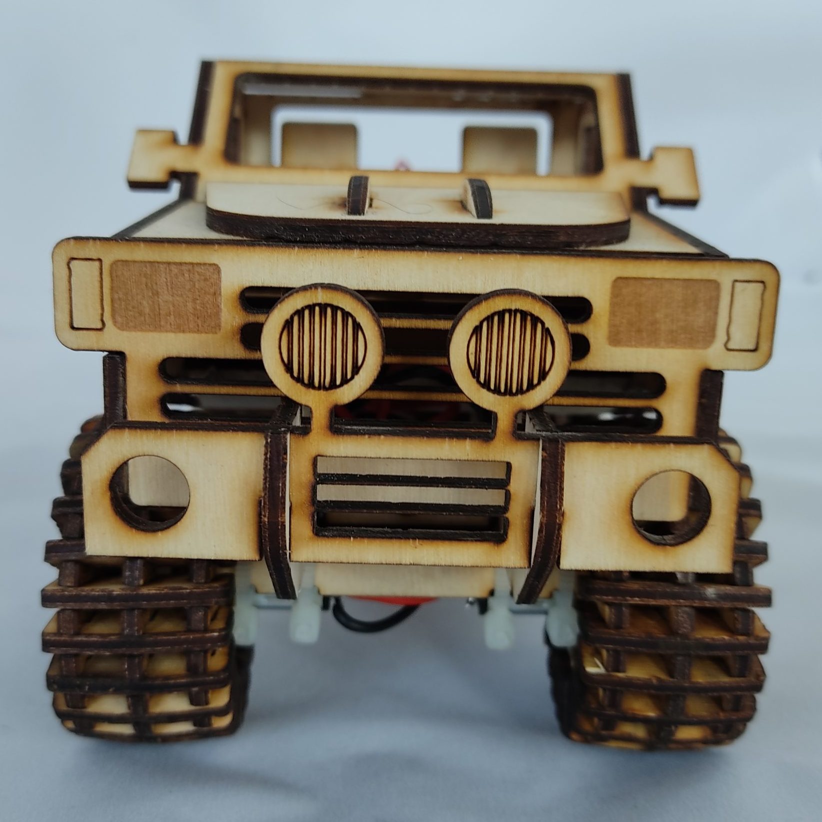

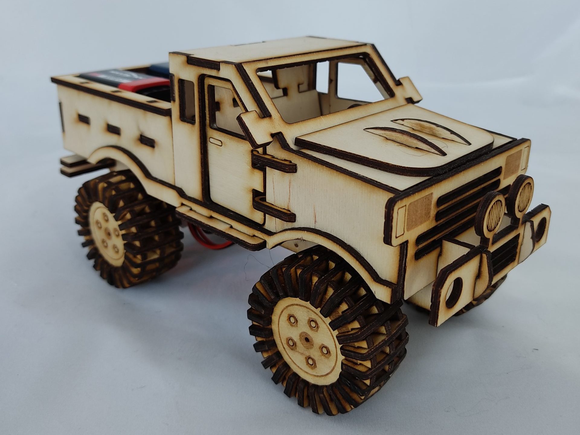
Content Holz RC Truck
In this tutorial, we will show you how to make our wooden truck with the following components:
- Laser cutter
- Glueing
- Electronics: Install Arduino and ESP32 board files.
- Soldering
- The truck in action
Production / Fabrication of the Wood Truck:
Not everyone has a laser cutter in the basement, consider buying the kit on our site and help a couple from Germany to run their store. We also offer nice personalization options at fair prices :).
The lasering of the truck takes about 1.20h and is shown in time-lapse in the video below:
Wood Truck gluing
Here we show you how to glue and assemble our wooden truck. You can use any wood glue, please only pay attention to the usage instructions (especially drying time), the color (white or transparent) and if necessary sufficient ventilation for drying. The assembly of the truck usually succeeds between 1-2h.
Electronic parts:
For the electronic components, following is required:
- Soldering Station
- Arduino IDE
- ESP32
- Stepper Motors
- Stepper Motor Card
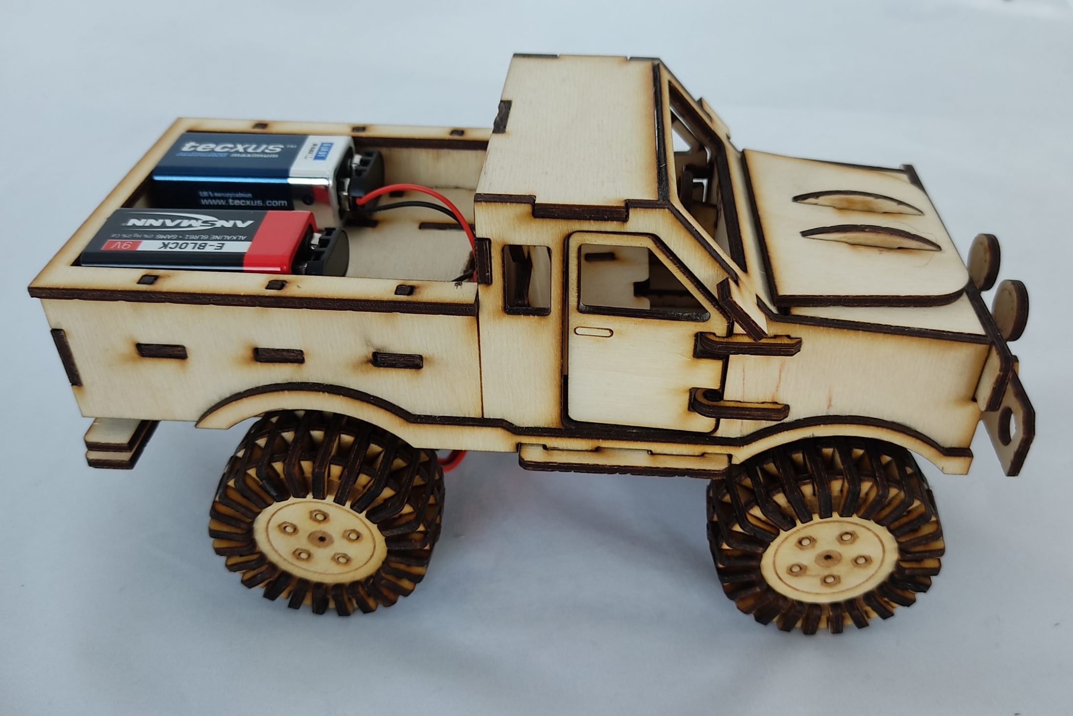
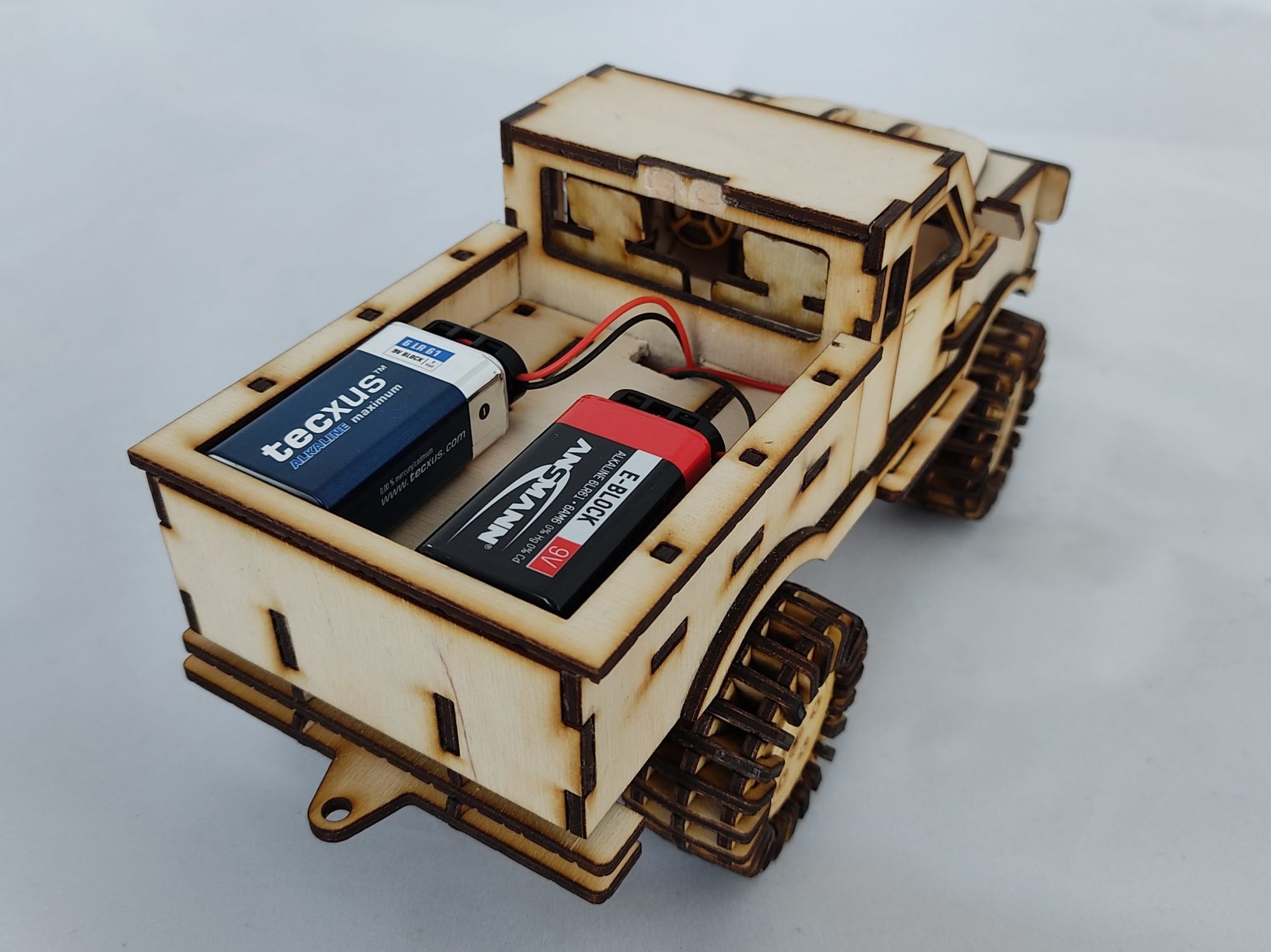
- Accus (9V)
- Charger
- Loudspeaker
- Loudspeaker card (PAM8302)
Please click on the respective links to get to the product suggestions (we do not earn anything from them).
Electronics: Installation Arduino
Please follow the official guide to install the Arduino IDE:
Electronics: ESP32 Microcontroller board files installation
Please follow the excellent tutorial from randdomnerdtutorials for installing the board files.
Klicken Sie auf den unteren Button, um den Inhalt von randomnerdtutorials.com zu laden.
Elektronics: ESP32 programming
Pinmapping of the ESP32
It is always helpful to have a look at the pin mapping of the used components. The digital-to-analog converter on GPIO pins 25 and 26 can be used as a signal source for the sound card. The remaining GPIO pins can very easily perform tasks like writing digital low or high (either 0V or 3V3).

Pinmapping L298N and Mini L298N
The mini version of the L298N is really much smaller. The mini version uses a similar chip, which can only draw less current, but for RC models really completely – so absolutely completely – sufficient. The larger version, however, has slight advantages (aside from size). The larger board has a 5V step-down converter, which is the ideal voltage for the ESP32. The ESP32 itself also has a 3.3V step-down converter, the AMS1117, which can be operated in a range of 5-12V without any problems. However, the down converter is a linear regulator and not a switching converter (just google it), so the efficiency decreases significantly at voltages much higher than 5V.
- Each motor is controlled by two GPIO pins, which are connected to IN1 and IN2 for motor A and to IN3 and IN4 for motor B.
- The pins only have to be digitally low and high. The pins only need to be able to write digitally low and high, i.e. 0V and +3.3V voltage.
- The single-phase stepper motors are connected to the outputs Motor-A and Motor-B. Several motors can also be connected together at the outputs. For example, the left wheels can be connected to Motor-A and the right wheels to Motor-B.
- The motors can be connected in any polarity, but the direction of rotation has to be considered, so that the truck will do what you want it to do :).
- For the correct direction of rotation, please refer to the GPIO pinout below.
For the especially interested reader we recommend to have a look at the datasheet of the L298N, but better not too long, it can be a bit very boring.


Pinout PAM8302 Sound Card:
About the sound card, all you really need to know is that you should only connect standard speakers with a resistance of 4-8Ohm (the most common ones) and the pinout looks like this:
- Ground: connect GND or 0V
- 2-5VDC: Connect operating voltage of 3.3V, what the
- ESP32 outputs.
- Shutdown: If pulled to GND, then the speaker is switched off. I would always recommend this, because the amplifier is poorly shielded and often picks up signals that are then only output as noise.
- Only Audio In+ is used because we play mono WAV files.
If you want to know more, you can download the datasheet of the PAM8302 below.


Program your ESP32 with a USB cable (and the correctly selected port) using the code below (version 29.12.2020). The code is open source and written by Lasercut24, if you continue to use it, please indicate the source. The truck receives its commands through this. Because of the long code only some snippets are presented here:
Code release notes like pinout:
/*Pin assignment:
* GPIO16: Mute PM8302 sound card on SD (Shutdown PIN)
* GPIO25: DAC (digital-to-analog-converter) on A+ pin on PM8302
* VCC of PM8302 on 3.3V
* L298N Micro stepper card: right wheels on MOTOR A output of L298N
* L298N Micro stepper card: LEFT wheels on MOTOR B output of L298N
* Right Motor: rmotorpinA = 25; rmotorpinB = 33;
* Left motor: lmotorpinA = 26; lmotorpinB = 27;
*/
/*
F: Forward : 70
B: Back : 66
S: Stop : 83
L: Left : 76
R: Right : 82
I: Forward right : 73
J: Back right : 74
H: back left : 72
G: forward left : 71
u: u-turn : 117
t: u-turn : 116
M: Sound1 77
N: Sound2 78
O: Sound3 79
K: Light off 75
Z: light on 90
*/
Receiving and sending of Bluetooth commands:
if (SerialBT.available()) {
incoming = SerialBT.read();
Serial.println(incoming);
counter = 0;
}
Processing of the commands:
if (incoming == 83)
{
Serial.println(„Stopping now“);
SerialBT.println(„Stopping“);
digitalWrite(rmotorpinA, LOW);
digitalWrite(rmotorpinB, LOW);
digitalWrite(lmotorpinA, LOW);
digitalWrite(lmotorpinB, LOW);
}
Generate sound files and upload to ESP32
- For editing the sound files it’s best to download the freeware Audacity: https://www.audacity.de/
- The ESP32 only has an 8bit digital-to-analog converter, which is a bit inferior to modern studio technology :)…., but perfectly adequate for fun here.
- Follow the YouTube video below to create the sound files and download them to the ESP32:
After you have created the WAV files, they still need to be converted to hexadecimal format.
To do this, download the GVIM text editor for Windows:
https://www.vim.org/download.phpAnd open your Command Shell / Input Console in Windows and enter the command: xxd -i mycrazywavfile.wav mycrazyhexfile.h

Windows will probably give you an error message now because the input console cannot access the VIM EXE. To do this, you must first set a path variable. To do this, enter Edit the system environment variables or path variable at the bottom left of Windows10 and open the suggestion. Then just follow this tutorial:
https://superuser.com/questions/1026685/setting-up-vim-under-win-10
Electronics: soldering
If you don’t have that much practice in soldering, maybe watch a short soldering course on YouTube – it won’t be necessary, but it’s very helpful. Please always make sure that the solder joints are already preheated before you add solder. Flux helps, but will not be necessary. The soldering tip tends to oxidize after prolonged use, use steel wool, a soldering tip reactivator or simply a new soldering tip from time to time.
Schematic for soldering the components:

The soldering of the individual components for the RC Truck can take some time – probably it will also happen that you have to solder times or possibly change the pinout in the Arduino IDE. This is not bad and just requires some patience. For clarity the connection of external LEDs was not shown on the schematic, that will follow later. For the wiring there are the following points to consider:
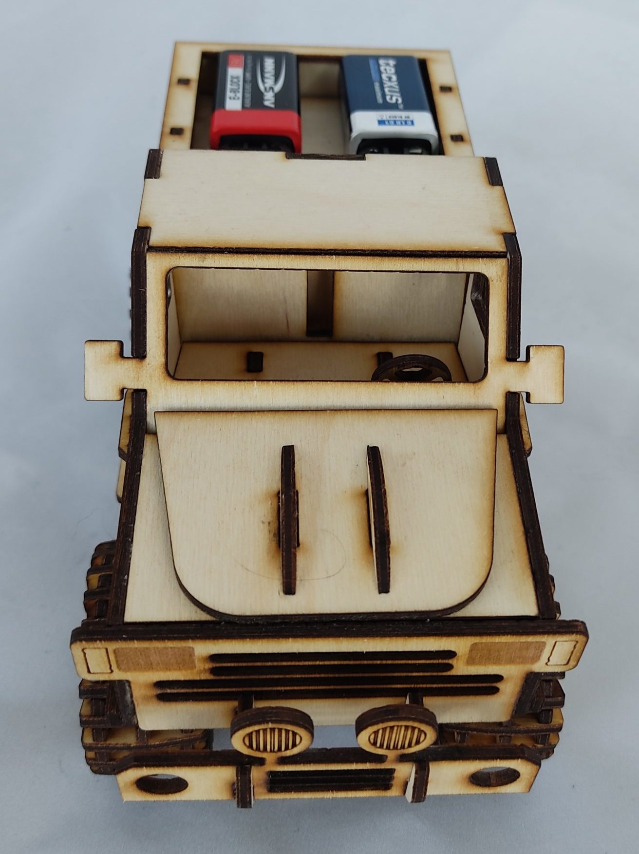
- ESP32 and stepper motor board are powered separately by a 9V block each. The motors draw so much current during startup that the supply voltage at the ESP32 would collapse and the Bluetooth connection would be lost because the controller resets itself.
- GND of the stepper motor card should be connected to GND from the ESP32. This is considered best practice in electrical engineering to avoid having unwanted voltage differences in the circuit.
- Be careful when soldering the motors, but the running direction can always be changed later in the Arduino IDE.
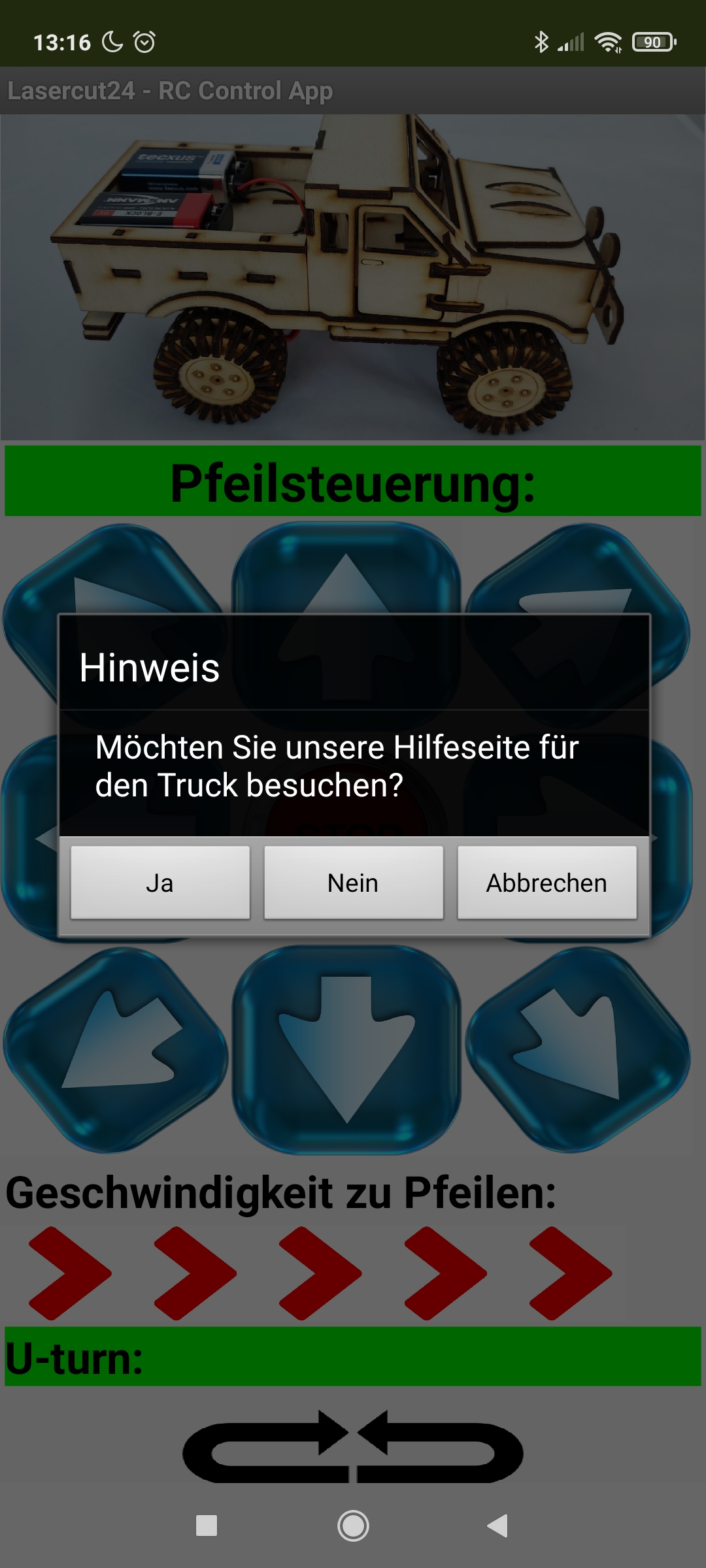
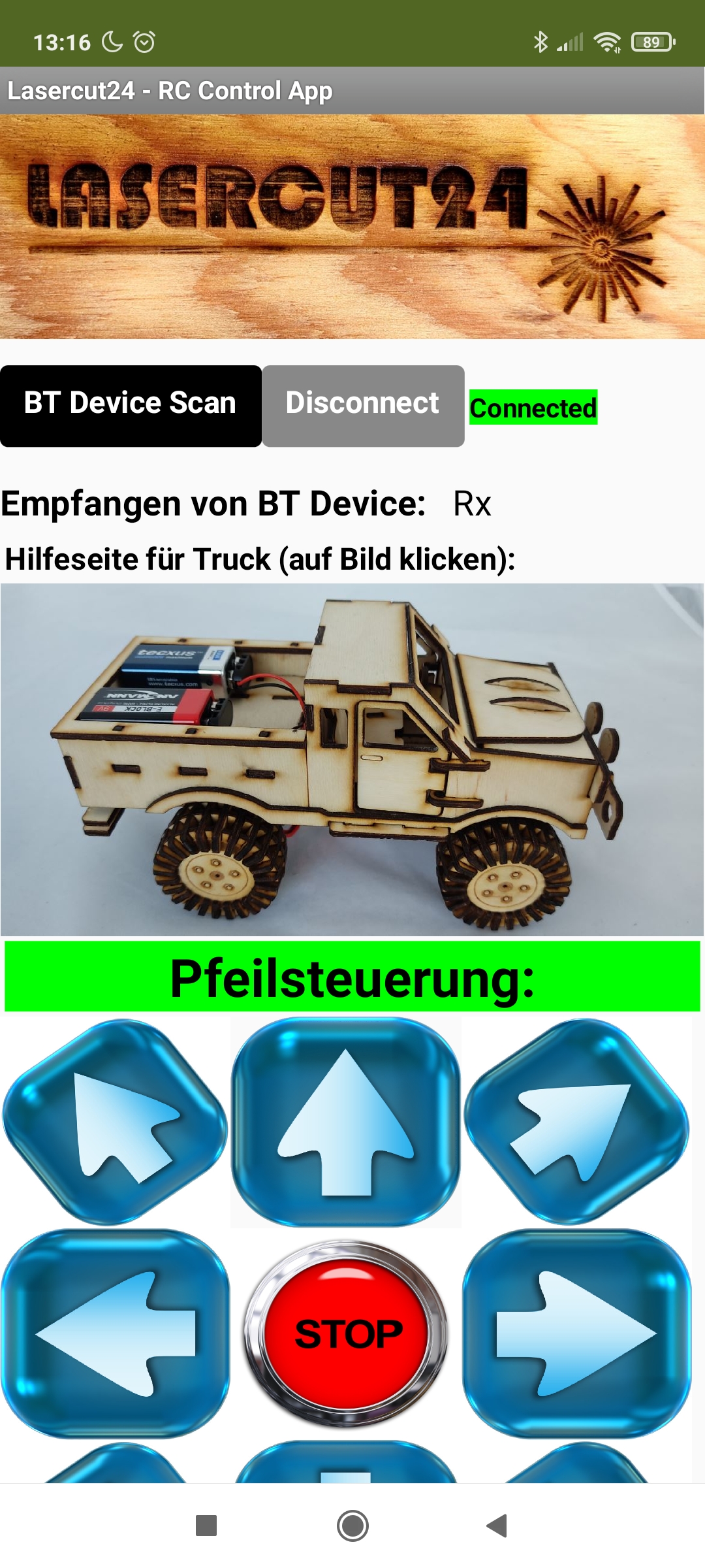
Elektronics: RC Control App for the wood Truck
Our Wooden Truck RC Control App is currently only available for Android devices on the Google Play Store. We update the functions of the app regularly. The app has the following functions so far:
- Connect Bluetooth, disconnect
- Link to our Help Page
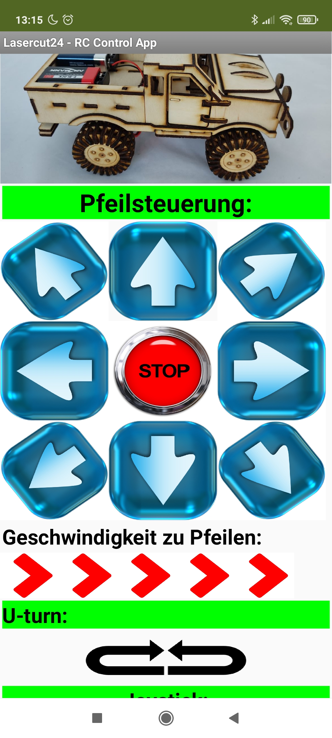
- Arrow control of the truck
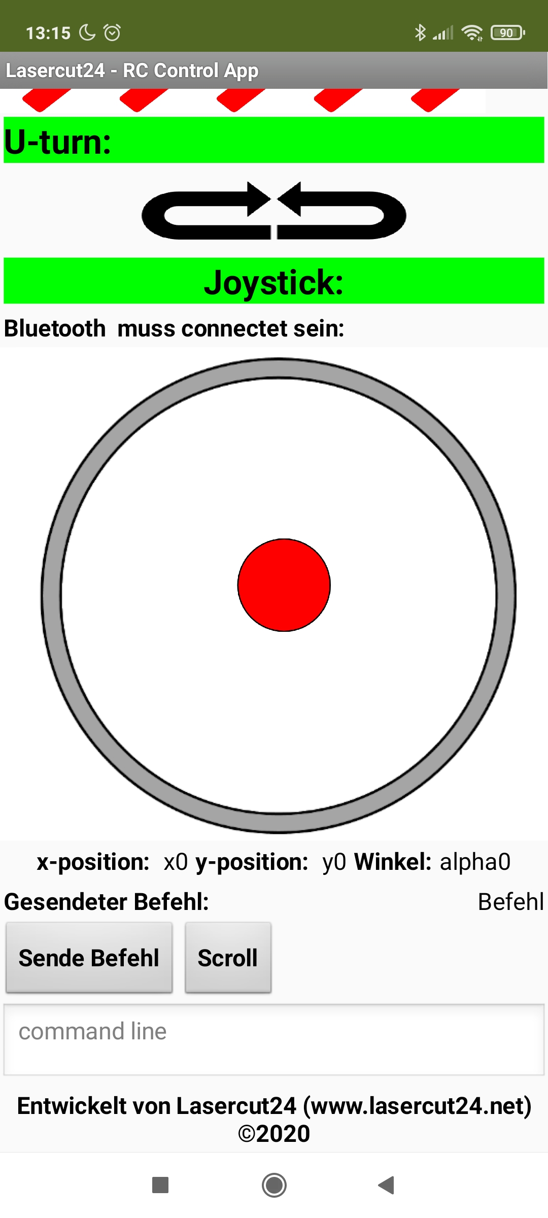
- Joystick control
- U-Turn clockwise and counterclockwise
- Send custom commands
- Light on/off (next release)
- Play music (next release)
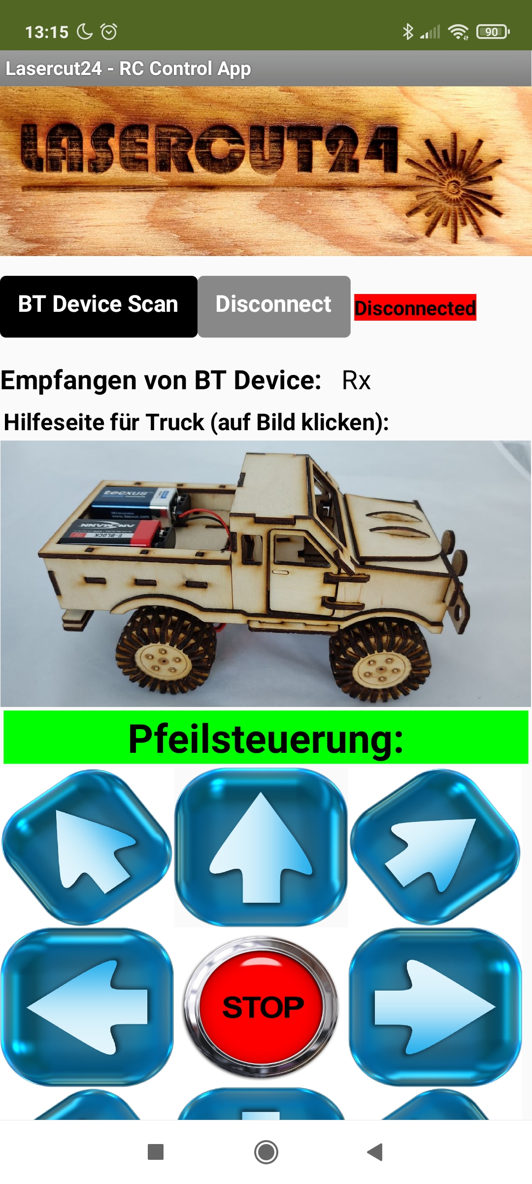
The app was developed by Lasercut24